Introduction
If you’ve spent time on any manufacturing floor, you’ve likely seen a vibratory bowl feeder in action—but do you truly understand the engineering behind this powerful automation technology?
Vibratory bowl feeders represent one of the most reliable and cost-effective parts handling solutions in industry, yet their performance can vary dramatically based on setup, maintenance, and optimization. Whether you’re looking to improve existing systems or implement your first vibratory feeder, understanding the technology at a deeper level can mean the difference between mediocre performance and exceptional results.
This comprehensive technical guide explores everything you need to know about vibratory bowl feeders—from the physics of vibration to real-world optimization strategies.
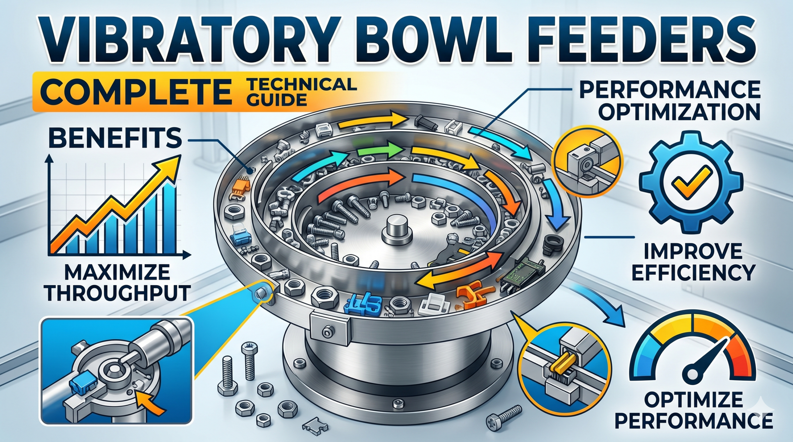
What Makes Vibratory Bowl Feeders Unique?
Unlike other parts feeding methods (pneumatic, servo-based, or manual), vibratory bowl feeders use controlled oscillation to continuously move components from a bulk supply into a production line. The defining characteristic is simplicity combined with effectiveness.
A vibratory bowl feeder consists of:
- The bowl – A specially designed container with a helical track
- The vibration source – Electromagnetic or pneumatic mechanism
- The helical track – Precisely engineered to orient and singulate parts
- The base structure – Supports and isolates vibration
The magic happens when vibration frequency and amplitude combine to move parts steadily upward while the track geometry orients them correctly.
How Vibratory Bowl Feeders Work: The Physics
Understanding the mechanics of vibratory feeders helps you troubleshoot problems and optimize performance.
The Vibration Mechanism
Most vibratory bowl feeders use electromagnetic vibration, powered by AC electrical current (typically 50 or 60 Hz, matching power line frequency).
Electromagnetic system operation:
- An electromagnet beneath the bowl creates a magnetic field
- The field attracts armature springs in a rhythmic pattern
- The springs flex upward and downward at the AC frequency
- This creates a vertical oscillation transmitted to the bowl
- A secondary mechanism adds a slight horizontal component for directional movement
Pneumatic vibratory feeders operate differently, using compressed air pulses to create vibration. While less common, they offer advantages in cleanroom and explosive environments.
Vibration Parameters
Three critical parameters define vibratory performance:
Frequency (Hz)
- Standard electrical frequency: 50 Hz (Europe/Asia) or 60 Hz (North America)
- Some specialized systems use variable frequency drives (VFDs) to adjust frequency
- Higher frequency = faster part movement but less gentle handling
- Lower frequency = gentler but slower throughput
Amplitude (mm)
- The distance the bowl moves in each vibration cycle
- Typical range: 0.5 mm to 4 mm depending on feeder size and application
- Greater amplitude = more forceful movement, better for jamming prevention
- Excessive amplitude = part damage and accelerated wear
G-Force
- The acceleration experienced by parts: G = (2π × frequency × amplitude)²
- Delicate parts require lower G-forces; robust parts tolerate higher values
- Modern systems typically operate at 2–6 G for optimal balance
The Helical Track Design
The bowl’s internal track is engineered to:
- Singulate parts – Separate bunches into individual pieces
- Orient parts – Position components in a consistent direction
- Move parts upward – Use vibration to gradually elevate them
- Discharge parts – Deliver properly positioned parts to the next process
Track design varies dramatically based on part geometry. A feeder for small fasteners looks completely different from one designed for flexible cables or fragile electronic components.
Types of Vibratory Bowl Feeders
Standard Vibratory Feeders
The most common type is suitable for medium-sized parts (5 mm–50 mm) in general manufacturing. They operate at standard electrical frequency with fixed amplitude.
Best for: Nuts, bolts, connectors, small plastic parts, springs
High-Speed Vibratory Feeders
Engineered for maximum throughput, these operate at elevated G-forces and optimized geometries to achieve 100+ parts per minute.
Best for: High-volume assembly (automotive, appliances, consumer electronics)
Precision Vibratory Feeders
Fine-tuned for accuracy and gentle handling, operating at lower G-forces with specialized track designs.
Best for: Electronics components, pharmaceuticals, precision instruments
Specialty Vibratory Feeders
Custom-designed systems for unusual part geometries, sticky materials, or extreme environmental conditions.
Best for: Irregular shapes, adhesive materials, temperature-sensitive components
Enclosed Vibratory Feeders
Fully enclosed for contamination control, noise reduction, and operator safety.
Best for: Cleanroom environments, food processing, pharmaceutical manufacturing
Key Advantages of Vibratory Technology
1. Reliability & Simplicity
With fewer moving parts than alternatives, vibratory feeders are remarkably robust. Electromagnetic systems have no motors, bearings, or complex mechanisms to fail.
2. Gentle Part Handling
Unlike mechanical conveying, vibration can be tuned to handle delicate components without damage. The continuous gentle acceleration is easier on parts than sudden movements.
3. High Throughput
Modern high-speed vibratory feeders can process hundreds of components per minute—matching or exceeding mechanical alternatives.
4. Cost-Effective
Initial investment is typically 30–50% lower than servo-based or pneumatic alternatives. Operating costs are minimal.
5. Flexibility
With relatively simple track modifications, vibratory feeders can handle a range of part sizes and shapes. Quick changeover between different components is possible.
6. Minimal Maintenance
Electromagnetic systems require virtually no maintenance beyond occasional track inspection and cleaning.
7. Compact Design
Vertical orientation means minimal floor footprint—critical in space-constrained manufacturing environments.
8. Noise Profile
Modern damping systems significantly reduce vibration noise, making them suitable for general manufacturing floors.
Performance Optimization Strategies
Getting maximum performance from a vibratory bowl feeder requires attention to several factors.
Track Surface Optimization
The track surface directly impacts part movement. Options include:
- Bare steel – Least expensive, suitable for hardy parts
- Hardened steel – Extends life for abrasive parts
- Polymer coatings – reduce friction, grease entrapment on parts
- Specialized liners – Custom surfaces for specific geometries
Optimization tip: Regularly inspect track surfaces for wear. A worn track can reduce throughput by 30% or more.
Frequency Tuning
While electrical frequency is fixed, some modern systems use variable frequency drives (VFDs) to optimize performance.
Strategy: Run at slightly above power line frequency (61–62 Hz instead of 60 Hz) to improve reliability and throughput. This small increase often yields 5–15% performance gains.
Amplitude Adjustment
The most effective lever for performance improvement is amplitude optimization.
Process:
- Start with the manufacturer’s recommended amplitude.
- Increase incrementally while monitoring part damage
- Find the sweet spot where throughput is maximum without part degradation
- Document the setting for consistent performance
Typical results: Proper amplitude tuning can increase throughput 20–40%.
Spring & Damping System
Vibratory feeders rely on precisely tuned springs to control movement. Spring degradation is one of the primary causes of performance loss.
Maintenance strategy:
- Inspect springs quarterly
- Replace springs showing loss of tension
- Check damping pads for deterioration
- Verify isolation mounts are functional
Cleanliness & Lubrication
Accumulated debris can dramatically impact performance.
Best practices:
- Daily: brush out visible debris
- Weekly: compressed air cleaning of the track
- Monthly: detailed inspection of all surfaces
- Avoid excessive lubrication (causes parts to stick)
Common Issues & Troubleshooting
Problem: Reduced Throughput
Likely causes:
- Worn track surface
- Degraded springs
- Debris accumulation
- Incorrect amplitude setting
Solutions:
- Clean the track thoroughly
- Inspect springs for loss of tension
- Check amplitude (may need to increase)
- Consider track resurfacing or replacement
Problem: Part Jamming or Backup
Likely causes:
- Undersized feeder for part volume
- Debris in discharge chute
- Track geometry worn
- Vibration frequency too low
Solutions:
- Check that the discharge path is clear
- Increase vibration amplitude gradually
- Inspect the track for damage
- Consider using a larger feeder model
Problem: Part Damage
Likely causes:
- Excessive vibration amplitude
- Track surface too rough
- Poor part geometry for feeder design
- Incorrect material selection
Solutions:
- Reduce amplitude incrementally
- Apply track coating (polymer) for a gentler surface
- Consult with the feeder designer on track geometry
- Consider a higher-speed feeder with gentler settings
Problem: Excessive Noise
Likely causes:
- Loose mounting bolts
- Degraded damping system
- Amplitude set too high
- Structural resonance
Solutions:
- Verify all mounting fasteners are tight
- Inspect damping pads
- Reduce amplitude
- Add an isolation platform beneath the feeder
Problem: Inconsistent Part Orientation
Likely causes:
- Track wear in specific areas
- Spring asymmetry
- Debris interference
- Part size variation
Solutions:
- Deep clean the track and inspect for wear patterns
- Replace springs if asymmetrical
- Implement incoming part quality control
- Consider track zone-specific resurfacing
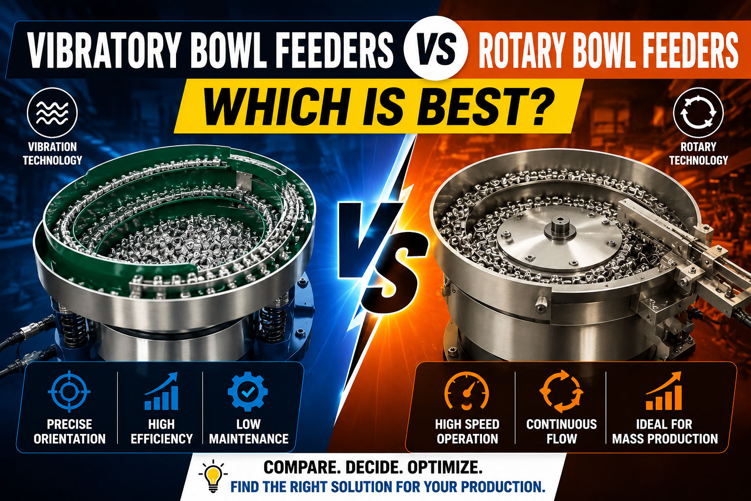
Vibratory Feeders vs. Alternative Technologies
Vibratory vs. Pneumatic
- Vibratory: Lower cost, simpler, good for most applications
- Pneumatic: Quieter, better for cleanrooms, higher operating cost
Vibratory vs. Servo-Based
- Vibratory: Reliable, low maintenance, moderate speeds
- Servo: Highest precision, complex, premium cost
Vibratory vs. Mechanical Conveying
- Vibratory: Gentle, compact, excellent part singulation
- Mechanical: Higher speed for some applications, higher maintenance
Verdict: For 80% of manufacturing applications, vibratory feeders offer the best balance of cost, reliability, and performance.
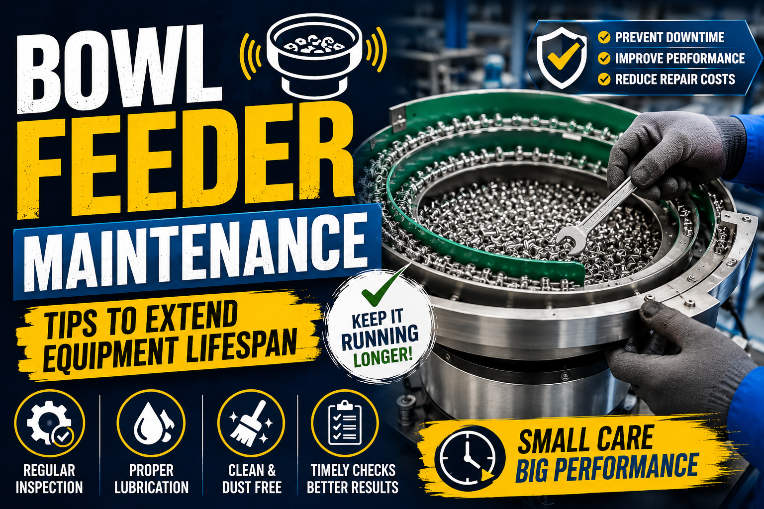
Maintenance Schedule & Best Practices
Proper maintenance extends feeder life and maintains peak performance.
Daily
- Visual inspection of track cleanliness
- Listen for unusual vibration sounds
- Check discharge for parts backup
Weekly
- Compressed air cleaning of the track
- Verify mounting bolt tightness
- Inspect for external debris accumulation
Monthly
- Deep cleaning of the entire feeder
- Detailed spring inspection
- Check the damping system condition
- Verify amplitude stability
Quarterly
- Professional inspection and adjustments
- Track wear measurement
- Spring replacement assessment
- Electrical connection verification
Annually
- Complete overhaul and certification
- Track refinishing or replacement if needed
- Spring set replacement
- Complete system rebalancing
Selecting the Right Vibratory Feeder
When choosing or upgrading a vibratory bowl feeder, consider:
Part Specifications
- Size range (length, width, thickness)
- Weight per unit
- Material (fragility, density, conductivity)
- Geometry complexity
Performance Requirements
- Required throughput (parts per minute)
- Orientation precision needed
- Feeding consistency tolerance
Environmental Factors
- Temperature extremes
- Humidity/moisture exposure
- Dust or contamination levels
- Noise restrictions
- Available floor space
Integration Needs
- Discharge height requirements
- Connection to downstream equipment
- Electrical power availability
- Control system integration
Budget Considerations
- Initial purchase cost
- Operating costs
- Maintenance & support availability
- Expected service life
The Future of Vibratory Feeding Technology
Modern vibratory feeders are evolving with:
Smart Monitoring: IoT sensors track vibration signatures, predicting maintenance needs before failure
Variable Frequency Drives (VFDs): Enable real-time optimization of frequency for different part types
Advanced Materials: New track coatings provide superior wear resistance and gentler part handling
Precision Control: Servo-integrated vibratory systems combining reliability with precision
Hybrid Approaches: Combining vibratory with other technologies for specialized applications
Conclusion
Vibratory bowl feeders have earned their place as the workhorse of industrial parts handling because they’re simple, reliable, and effective. Understanding the technology at a deeper level—from vibration physics to optimization strategies—allows you to extract maximum performance while minimizing downtime.
Whether you’re troubleshooting an existing system, planning an upgrade, or implementing vibratory feeding for the first time, the principles in this guide will help you make informed decisions and achieve superior results.
Ready to optimize your vibratory feeder system? Our experts can assess your current setup, identify improvement opportunities, and guide you toward peak performance. Contact us today for a complimentary system evaluation.
Leave a Reply